Radio microphones
Technical information ...
ALL
BRANDS
Radio
frequencies: The
frequencies made available depend on the type of business
the user is involved in (e.g. Theatre, Broadcast, Film,
Entertainment, etc.). Many of the frequencies authorised
by the D.T.I. interfere with each other, so where more
than one radio microphone is to be used in a location, we
take every precaution to provide a combination of
frequencies that work correctly together. However, we
cannot guarantee that there will not be interference
from, or to, other radio equipment in the area (taxis,
walkie talkies, broadcasting, commercial communications
systems, other radio microphones in the vicinity). If
interference is encountered, (usually evident as a
varying whistling noise called 'birdies'), we may be able
to offer you an alternative system. Most frequencies are
made available on a 'secondary' basis, which means that
if the radio microphone interferes with any other
licensed radio user, then the radio microphone user must
cease transmission. Fortunately, this is an exceptionally
rare occurrence.
Batteries: Systems are
supplied with batteries in a usable condition. It is the
user's responsibility to keep a check on battery
condition, and provide replacements as required. Note
that Micron systems with only one battery must
only be replaced with Alkaline PP3 batteries, (e.g.
Duracell, Gold Seal, etc.). Micron transmitters send an
inaudible signal to their receivers when their battery
level becomes low. This is apparent as a flashing of red
lights (at 1 Hz), to alert the operator to the problem.
Not all PP3 batteries are the same size! When replacing
batteries in Micron hand-held mics, take care to ensure
that the battery is making a permanent contact with the
two terminals (a small piece of cardboard may be wedged
behind small batteries to push them against the
terminals). Use your rehearsal time to calculate
convenient breaks for battery changes, making allowances
for extended performances and aiming to change batteries
within half the quoted life if possible.
Switching
On & Off: Micron
Hand-held & Sennheiser pocket transmitters have
On/Off switches. Micron pocket transmitters are only
switched 'On' by the process of connecting the
microphone. To avoid producing unwanted noise in the
audio system, check that the volume from the receiver is
not 'turned up' before the transmitter is switched 'On',
and conversely, 'turn down' the receiver's volume before
switching 'Off' the transmitter.
When a receiver is On while its transmitter is Off, there
is often a loud sound of white noise heard. This is quite
normal but can be damaging to ears and loudspeaker
systems, so care must be taken to ensure that the volume
from a system that is not being used is 'turned down'. In
certain cases, this white noise may even be heard faintly
in adjacent receiver modules in multiple receiver racks,
and can even 'break through' from one channel of a mixer
to another!
When using more than one system together, be warned that
by switching On or Off a transmitter, a brief but loud
noise may be produced in any other receiver
operating at that moment. (If costume changes necessitate
switching transmitters Off, and if the dressing room is
near enough the receiver antenna for these switch-on
noises to be heard, try removing the transmitter antenna
before switching off, and replacing it after switching
on).
Diversity
Receivers: These
receivers actually consist of two completely independent
receivers tuned to the same frequency. Each receiver will
be connected to separate antennae. There is an automatic
system which blends the sound from both of these
receivers to take advantage of whichever one is being
received with the stronger of the two signals at any
moment in time.
This feature of diversity receivers is necessary because
the transmitters produce radio signals which reflect off
walls, etc., and cancel out the original signal at
certain points in the room. (In reflective steel clad
studios, these cancellations appear at œ wavelength
intervals). As the transmitters move, so these 'dead
spots' move, and when one passes an antenna, the signal
is momentarily lost, often producing a 'pop' or a
'fizzst' noise. Even outdoors, the signal can disappear
completely in some spots. By using a diversity receiver,
it will generally be true that one or other antenna will
receive a strong signal. In cases of interference, the
Micron diversity receivers also have monitoring
facilities which, with the transmitter switched off, can
assist in quantifying the strength, frequency and
direction of the interference.
Receiver
Antenna Positions:
The best position for the antenna will be right next to
the transmitter.
The received signal strength falls off rapidly as the
distance between receiver and transmitter is increased.
In general, good positions will be high, away from large
metal surfaces, and in line of sight of the transmitter,
particularly avoiding any metal objects in between
transmitter and receiver antennae. As it is clearly
impossible to see radio signals, some experimentation can
be helpful in avoiding 'dead spots'. The receiver's
meters are vital in finding positions of consistently
strong signal strength.
In the attempt to place the receiver antenna close to the
transmitter, the use of long antenna leads should be
avoided, as there is approx. 10dB loss of a 180MHz signal
in 100m of low loss co-ax cable. It is better to use long
audio cables from the receiver, than long radio cables to
it.
Where a diversity system is being used, the two antennae
may either be used in identical manners (similar
positions but spaced a few meters apart and with
different orientations), or be used in complementary
positions, (e.g. one directional antenna at the back of
an auditorium pointing at a stage, and one
omni-directional under the stage).
Directional antennae (Yagi) are available on request, and
while giving a few dB s of additional signal strength in
the direction they are aimed at, they provide many dB s
of attenuation of unwanted signals from the sides and
from behind the forward field of pick-up. This property
greatly helps in reducing interference, and is
particularly useful where long transmission ranges must
be used. Beware that the wavelength of some VHF systems
may render these antennae too unwieldy for some
applications.
During your rehearsal do remember to monitor the
receivers' signal strength meters to locate any dead
spots, and to move the receiver antenna as required. This
will be as important to achieving repeatable results as
will attention to the audio quality.
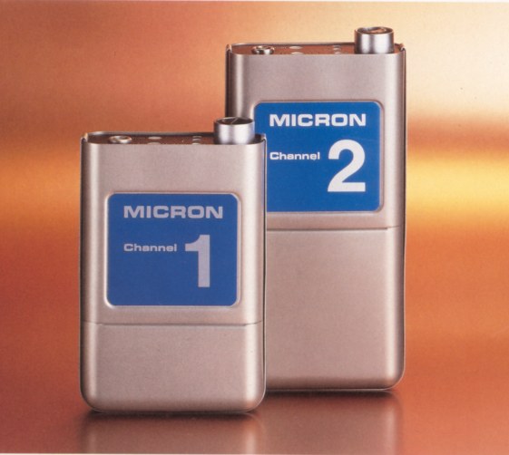 MICRON
POCKET TRANSMITTERS MICRON
POCKET TRANSMITTERS
Micron
pocket transmitters (pics, left) are
available with a variety of microphones and other inputs.
The most popular are the Sony ECM 50 & ECM 55 series
of clip-on lapel mics, the Sennheiser miniature MKE-2
which can be taped to the head or body, and input leads
for other microphones such as Shure SM10 head-worn mic
(with microphone boom in front of the mouth) and
Sennheiser MKH 416 gun mic for remote outdoor work.
These transmitters are switched ON whenever the
microphone is connected. The microphone should therefore
be unplugged at the end of a session. The antenna
connects on the top of the transmitter, at the opposite
side from the microphone, and should be kept reasonably
straight and allowed to hang freely, away from the
wearer's body and from the transmitter's case. The
battery compartment can be opened by pushing then
twisting the end of a small slotted screwdriver or Yale
style key in the opening on the bottom of the pack. The
unit uses one or two PP3 batteries. If only one battery,
then it must be alkaline. Each alkaline PP3 can provide
up to 8 hours operating life, the 'low battery' warning
signal being transmitted when the battery falls to 6.5
volts - at which time the battery should be changed
within about 15 minutes.
The controls on the top of a pocket transmitter allow the
level to be set by a small screwdriver potentiometer and
2 LEDs. The LEDs will only operate while the
"SET" button is pressed, in order to conserve
battery power.
The "SET" and "TONE" controls can be
locked in their ON positions by pushing them in and then
slightly sideways - don't forget to release them when you
have finished adjusting the transmitter level!
There is a volume adjustment on the top of the unit near
the microphone socket. To help in adjusting the volume,
press the small white SET LEVEL button, and lock it in by
pressing it sideways. Adjust the level so that typical
speech illuminates the -10 LED, but not the 0 LED. Do not
forget to release the button when this has been done.
To confirm that there is a good radio link between
transmitter & receiver, there is a small white TONE
button on the top. This can be operated by pressing the
button in. This button can also be locked in the On
position, and will be the cause of a continuous 1k Hz
tone at the receiver, at 0dBm (PPM 4).
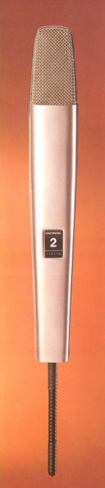
MICRON
HAND-HELD TRANSMITTERS
The aerial screws onto the threaded stud on the base of
the unit. These are switched On/Off by way of a three
position switch on the base. There is also a three
position volume switch on the base with unusual markings.
The 'loud' position makes the system quieter, and is made
for loud voices. The 'quiet' position is similarly for
quiet voices. There is a 'mute' position to the On/Off
switch, which allows the user to silence the microphone,
without turning off the radio signal which would produce
the undesirable noises mentioned under On & Off,
above.
 The battery
compartment is opened by unscrewing the large slotted
screwhead on the side of the body. Batteries must
be alkaline PP3s, and battery life is approximately 8
hours maximum, but allowances should be made for much
less than this. The same 'battery low' signal is
transmitted to the LED display on Micron receivers as
with portable receivers, at which time the battery should
be changed within a few minutes. The battery
compartment is opened by unscrewing the large slotted
screwhead on the side of the body. Batteries must
be alkaline PP3s, and battery life is approximately 8
hours maximum, but allowances should be made for much
less than this. The same 'battery low' signal is
transmitted to the LED display on Micron receivers as
with portable receivers, at which time the battery should
be changed within a few minutes.
For outdoor use where wind noise may be a problem, or
even in certain indoor situations where unwanted low
frequency noise is present, a bass roll-off switch with
three positions is provided. This is in the battery
compartment next to the terminals, and can be adjusted
with a small screwdriver or match, etc. The battery
terminals bend a little each time a battery is inserted.
Gently pull them back towards the battery if they appear
to be making contact without much pressure.
SENNHEISER
POCKET TRANSMITTERS
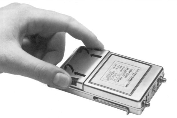
(See pic, right).
The battery compartment is opened by holding the
transmitter in the palm of one hand with the identity
label uppermost, and with the thumb and forefinger of the
other hand, pulling the two black ribbed finger-holds
down, towards the bottom of the transmitter, and pulling
the hinged cover downwards.
The transmitter takes 3 x AAA size batteries, 1.5v. Care
should be taken to check that the springs which hold the
negative battery terminals in place are not pushed against
the body of the transmitter which could "short
out" one or more batteries!
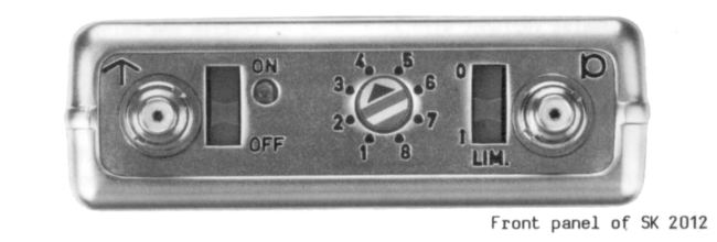
The controls for these transmitters are on the top panel
inbetween the microphone and antenna sockets. These
sockets are of the same type and size, and are
distinguished by the symbols marked next to them (see
pic, below - antenna symbol on the left, microphone on
the right). They have an On/Off switch located next to
the antenna socket, a screwdriver volume control in the
centre and a limiter In / Out switch next to the
microphone socket.
To assist in setting a working level on the transmitter,
the receiver's LED display can be switched to show
'deviation' which is effectively the received audio
signal level. This display will allow you to optimise the
transmitted audio level (within the available dynamic
range).
MICRON DIVERSITY RECEIVERS
There are On/Off switches on the front and back
panels of these units.
The audio connections offer a microphone level output
from the male XLR on the rear, (-53dBV, balanced &
floating), and a line level signal from a jack
socket, also on the rear panel ( 0dBm, unbalanced) which
will accept a P.O. jack, or two or three-pole A gauge
jack. As there is no adjustment over this level, be sure
to use the correct socket for your associated equipment's
input. Always use the diversity mode of operation, unless
there is some particular interference product appearing
from one antenna that can be silenced by switching
exclusively to the other antenna. On the separate Micron
diversity receivers (MDR 3 or MDR 530), the audio is
monitored using the small 'A-diversity-B' switch, which
selects which receiver is monitored on the headphone or
loudspeaker. The speaker switch and volume control allow
the operator to monitor the microphone and the reception
conditions of each antenna's tuner, independently of the
subsequent sound system.
When the transmitter battery is low but just usable, the
receiver's red LED columns will pulsate once a second,
from left to right. If the receiver is also being powered
by batteries (12v), a low receiver battery warning
appears on the top two green LEDs, which will flash. To
power the receiver from a D.C. source, use the 240 degree
5-pin DIN socket, Pin 2 negative, Pin 4 positive, input
voltage range 10œ - 15 volts. Typical current per
channel is 150mA.
Never use these receivers with poor or no earth on
the mains supply, the interference suppressor can pass
electrical noise voltages to the chassis, which will can
be dangerous if touched and not properly earthed through
the mains. When using racked receivers, note that the
numbers against each of the audio output sockets on the
rear panel indicate the physical position of the
corresponding receiver module in that rack, they do not
indicate the channel number of the operating frequency.
The channel numbers appear on the transmitters and the
front of the receiver modules.
MICRON
PORTABLE RECEIVERS
There is a multi-function switch on the front of these
receivers, whose function has slightly changed over the
years, and has been internally linked to provide the
required operation, in later models. The functions are
explained on the panel on the top of the receiver, but
the differences only apply to the centre 'off' position.
On some models, this switches off the receiver
completely, saving battery life, and avoiding 'white
noise' when the transmitter is 'off', but it also causing
an audible thump when switched 'on' & 'off'. On other
models, the centre 'off' position only switches off the
LED display, saving battery life at the receiver; in
these units, there is no 'Off' switch. The other two
positions select the function of the LED display-: The
'up' position displays transmitter information (signal
strength, tuning, low battery warning - 6.5 volts or
less); The 'down' position displays receiver information
(battery condition).
The antenna input is by way of a BNC connector on the
back, which in portable applications will accept direct
connection to a half dipole.
The audio output is from a 3-pin locking Preh (DIN)
connector, balanced across pins 1 & 3, with screen
and centre-tap on pin 2. Adaptor leads to XLR 3pin male
are normally provided, with the signal balanced across
XLR pins 2 & 3, and with screen and centre tap on pin
1. Audio output is also available on a TRS 'B' gauge jack
socket, via a screwdriver adjustable level control on the
side of the unit (this will drive high impedance
headphones at an adequate level for most purposes) note
that the audio appears across the tip and ring, with the
sleeve not connected.
The unit may be powered through the 5 pin Preh (240
degree, DIN) locking connector in a variety of ways: 12
volts DC across pins 4(pos) & 2(neg), or 18-25 volts
DC across pins 5(pos) & 1(neg). This is compatible
with Micron MMS1 mains power supply units, Micron battery
packs (containing 8 x AA size 1.5 volt batteries which
fit into the receiver carrying case), the Micron power
output socket on some receiver rack units, and 12 volt
lead-acid batteries with the appropriate leads. The
current requirement of the MR510 receiver with LED
illuminated is approx. 55mA, (and with LEDs off, 45mA.).
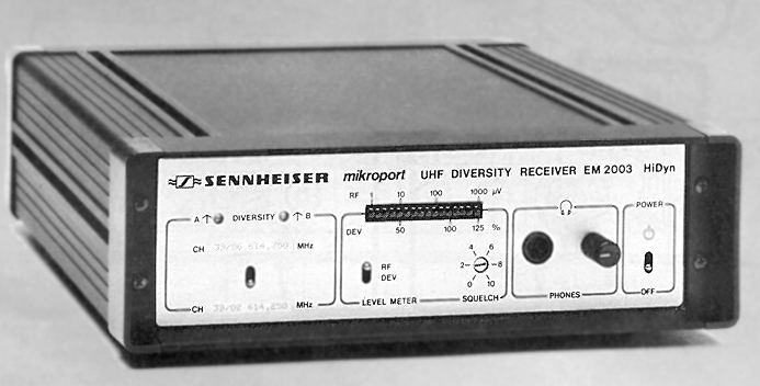
SENNHEISER
DIVERSITY RECEIVERS
The mains On/Off switch is on the front panel. The mains
socket does not have an earth pin, the ground being taken
from the audio cable screen. Usual 3 pin IEC mains
sockets will fit the two pin socket correctly. The audio
output is available on an XLR male socket, (balanced
& floating at low impedance) on the back panel, next
to a screwdriver level control. This socket is capable of
producing a line-level output ( 0dBm ), if required.
 The input
sockets for the RF antenna on the rear panel are not
straightforward, and require some care. The two
(diversity) receivers within each unit are identified as
A and B, and it is vital for proper diversity operation
that separate antenna inputs are provided to each of
these. There is only one socket for the 'B' receiver, but
two for the 'A' receiver, one being an input, and the
other an output. This arrangement allows two diversity
receivers to be housed in a single 19" rack with
only two antennae whose signal are split as follows:- The input
sockets for the RF antenna on the rear panel are not
straightforward, and require some care. The two
(diversity) receivers within each unit are identified as
A and B, and it is vital for proper diversity operation
that separate antenna inputs are provided to each of
these. There is only one socket for the 'B' receiver, but
two for the 'A' receiver, one being an input, and the
other an output. This arrangement allows two diversity
receivers to be housed in a single 19" rack with
only two antennae whose signal are split as follows:-
One antenna is connected to each receiver's 'A' input,
then two short BNC link leads connect each receiver's 'A'
output to the other receiver's 'B' input.
Most antennae are completely passive devices, but the
Sennheiser directional UHF antenna, which looks like a
flat black plate, is an active device, which needs to
draw power from the receiver. That power is available on
the 'A' and 'B' inputs to each receiver, and the wiring
method described above will operate perfectly.
The front panel LED meter can be switched to indicate
either the radio signal strength, "RF", or the
audio signal level, "DEVIATION". The front
panel "SQUELCH" control allows you to adjust
radio signal strength level at which the output becomes
muted. This is also a screwdriver adjustment, where the
lower the number on the control indicates the lower the
RF level at which the mute will operate. The final front
panel control is the headphone monitoring socket and
level control.
R.F.
DISTRIBUTION AMPLIFIERS
These allow the signal from one antenna to be routed
to up to four receiver inputs. These amplifiers must be
powered from a Micron 12v power supply (or other 12v
outlet). There are no controls and no indication of the
presence of power. Remember that for useful diversity
operation, each channel of a receiver must receive
signals from a different antenna, so where r.f.
distribution amplifiers are being used, there must be one
for each antenna.
For example, in a system of four diversity receivers, one
antenna would be connected to an R.F. distribution
amplifier which in turn would be connected to the four
'A' inputs of each receiver, and a second antenna would
be connected to another distribution amplifier, in turn
connected to the four 'B' inputs of each receiver.
ANTENNA
TYPES
There is a
variety of types of aerial, each suited to different
applications:-
V.H.F. helical half dipole. This is the
most compact, and is generally supplied with a right
angled BNC socket for direct connection onto the rear of
a portable receiver; this is usually the antenna used for
mobile work. It is limited by being situated only where
the receiver happens to be placed, though they can and do
often give excellent results even in fixed installations.
Experimentation will confirm whether an adequate signal
is being received or not.
V.H.F.
helical dipole. This is the
most frequently used receiver antenna, consisting of a
central connector with BNC and crocodile clip, and two
threaded sockets for attaching the two halves of the
dipole. (The threaded studs that connect the dipoles to
central connector can un-screw and disappear - sawing the
head off 2BA bolt will make a perfect replacement). These
can be attached to walls, etc. using the crocodile clips,
and in diversity applications can be set at differing
orientations, at opposite sides of the performance area.
Where possible, avoid attaching them to earthed or other
metal objects such as water pipes, but if only earthed
fixings are available, they may offer better reception
than an unearthed position twice as far away or out of
sight. For portable work, the dipole can be clipped to
the shoulder strap of the recorder, and probably give
better reception than a half dipole under the receiver
(at leg height).
V.H.F.
Yagi. These 3
element antennae are superb in applications where their
pick-up from the front gives useful directional
properties. This can help eliminate much of unwanted r.f.
signals from the sides and rear, if the transmitter(s)
are always going to be within the same few degrees of
sight from the front of the Yagi. However, they are
large, unwieldy to transport, unsightly to place in
auditoria, and impossible to use with mobile receivers.
For diversity operation, two antennae must be used, and
although they need not both be Yagi, the other should
still have a reasonable chance of receiving a strong a
signal in order to be useful.
An example application of Yagi antennae is at a sports
event with a number of transmitters in the stadium, and a
Yagi on a mast on top of the sound recording vehicle
outside the grounds, connected to a rack of several
receivers. In this case the one Yagi antenna is pointing
at the area where all the wanted transmissions shall be
coming from, and rejecting all the other r.f. that may be
'hitting' the high mast position from all other
directions. Another application is a water-sports event
where the distance between the land-based commentator,
and the P.A. system may be quite great, and where the
waterborne commentator may be even farther away, but
always in the same direction so that a Yagi may be aimed
at both commentators.
U.H.F.
Yagi. These have
all the benefits of directional antennae mentioned above,
but are more compact than V.H.F. yagi. They consist of
about six short metal elements on a central rod, of about
half a meter in length, which can be clamped to a mast or
bar. The r.f. terminal is BNC. For diversity operation,
two antennae must be used, and should both be pointing
towards the area where the transmitters will be used,
though each from a different direction. U.H.F. signals
are severely attenuated by objects in the line of sight
between the transmitter and receiver, so a directional
antenna can be vital in achieving a usable signal
strength.
U.H.F.
Ground-plane. This is a
compact arrangement of three 'legs' radiating outwards
and slightly downwards from a central connector, with a
fourth 'leg' pointing upwards. This is omni-directional,
but can achieve good reception if mounted above most of
the 'earthy' objects in the area. It is attached by a
3/8" thread on the hub, which suits most microphone
stands and fittings, and can also be used with special
'G-clamps' available with a 3/8" microphone thread.
The r.f. connector is a UHF threaded socket, supplied
with an adaptor to BNC.
U.H.F.
directional plate.
This large plate should be mounted vertically, with its
arrow pointing towards the area of strongest reception.
It offers the same directional advantages as the V.H.F.
Yagi mentioned above, but is small enough to be used in
any auditorium. This is ideal even for use at the side of
a stage in theatre applications, where the rejected
signals from the sides and rear may just be the signal
reflected off the walls, but which may contribute to
cancellations if a non-directional antenna is used. This
antenna is attached by a 3/8" thread, which should
suit most microphone stands and fittings. It should be
mounted with the 3/8" thread socket facing
downwards. The r.f. connection is BNC.
All antennae (transmitters and receivers) have a length
that is selected to suit the frequency of operation, and
in some systems, there may be a variety of frequencies in
use, requiring a variety of lengths of antenna. In the
case of helical dipoles, it is not possible to tell how
long the arms of the antenna are by measuring them,
however there is often a coloured band on two of the
frequency bands: red for 185 - 205MHz, and green for 205
-225MHz. No coloured band is probably the 168 - 186 band.
Note that a tolerance of plus or minus 5% is quite
acceptable, and 10% should still provide reasonable
results if necessary. (Better with one antenna in a good
position even if its length is 15% 'wrong', than an
antenna position that is not in line-of-sight). The
U.H.F. ground-plane has adjustable 'legs' which are
marked in MHz and whose length must be tuned to the
operating frequency.
The Aluminium Yagi antenna is of fixed length, but can be
given a wider tolerance of, say, plus or minus 10%. The
straight transmitter antenna will be either a quarter or
a half the wavelength, and for the technical, wavelength
(in meters) = 300 / frequency (in MHz). So for example,
for a frequency of 177 MHz, the wavelength will be 1.69
meters, therefore the length of a quarter-wave antenna
will be 1.69 / 4 = 422.5 mm. This should be good for all
frequencies in the range 168 - 186 MHz. In emergency, a
low frequency's long antenna can be cut to the required
length of a higher frequency's shorter antenna.
TROUBLESHOOTING
AUDIO PROBLEMS
Feedback. This is the
enemy of many productions using tie-clip microphones with
a P.A. system. Careful speaker placement, microphone
placement, equalisation and skilful use of the faders are
the principal techniques; frequency shifters,
supplementary 'fill' speaker arrays, phase cancelling
speakers, etc., etc. are available in difficult
situations. In all these cases, it is helpful to ignore
the radio part of the link, while trying to obtain a
satisfactory sound balance, and consider the microphones
as wired omni-directional mics. In the case of continual
howl from a Micron pocket transmitter, check that the
1kHz test tone button has not been locked 'in'. Also
check that a line level signal from the receiver is not
being connected to a mic input on the mixer.
'Birdies'. (Changing
whistling noises). This is a result of using a
combination of radio frequencies that produce
intermodulation frequencies that are picked up in one of
the receivers. It may occur when three or more
transmitters are used together which do cannot, in fact,
operate together for this reason, or it may be the result
of some external radio source that is creating the
intermodulation frequency along with one of the radio
transmitters. This is not really an audio problem, but a
radio problem, and although it may be cured by revising
the relative positions of the transmitters, or of the
receivers, or experimenting with the antennae's
positions. It may become necessary to exchange one or
more systems for a system operating on another frequency.
Audio
level changes. When this
happens gradually, it is generally the distance between
the microphone and speaker's mouth that is changing. When
this happens with sudden and sharp jumps in level, then
it is probably the result of the Complementary Noise
Reduction System in the receiver loosing track of the
incoming signal for a moment, and therefore failing to
correctly follow the corresponding gain adjustments in
the transmitter. In this case look for faulty antennae
and antenna connections, antenna cable or poor receiver
antenna positioning relative to the transmitter antenna.
Also check for good received signal strength at the
receiver. Check for loose audio connections, which can
'trick' the noise reduction system in the same way. There
may be a weak microphone connection to the transmitter.
Distortion. With loud
voices, particularly singers, or tie-clip mics fitted to
instruments, it is likely that the signal level will
distort or clip at some point in the system. All the
transmitters have a level control or switch to reduce the
volume transmitted.
No audio. Check
batteries and all connections from the microphone through
to the mixer, using the meters to monitor received signal
strength, and headphones to monitor the audio in the
receivers, where possible. By systematically following
the signal from microphone through receiver to the mixer,
it should be possible to identify where the sound path is
broken - usually a switch has to be turned to the correct
position or a cable has to be plugged into the correct
socket, somewhere.
One
microphone's signal is heard on another's receiver. Check that
the transmitter whose signal is being 'invaded' is
switched 'On' and with a good antenna connection and good
received signal strength. (Some receivers will try to
lock on to another signal if their own transmitter is not
'On'). Try moving the transmitters apart, to more than
half a wavelength of each other. If the transmitters are
too close together, some curious intermodulation products
can be created from the combination of the two signals with the other frequencies present within the
transmitters. If two transmitters must be used close
together, there may be another pair that works better
close together in your studio or stage. Check that the
combination of frequencies (and types of transmitter) is
capable of operating simultaneously.
Loud
white noise heard instead of audio. Presumably
there is no transmitter operating on that frequency, but
the background RF noise level is enough to 'lift' the
automatic mute (or 'squelch') control. Check transmitter
is On, with good batteries and antenna.
Crackling
and/or intermittent audio. Check
transmitter microphone and antenna connections. Try
substitute mic & antenna. If noise occurs when
transmitter passes through certain places or angles, try
to improve the receiver antenna positions relative to the
receiver positions (the closer they are to each other the
better). Check for normal audio causes, such as mains
borne interference, bad connections, bad grounding, etc.
Back
to Midnight Electronics home page
|